Okay, I’ll be the first to admit when I’m wrong – or when I provide wrong information.
A few days ago, I commented that no one has yet offered the ability to split out Ethernet and Fibre traffic at the chassis level (as opposed to using a top of rack switch.) I quickly found out that I was wrong – IBM now has the ability to separate the Ethernet fabric and the Fibre fabric at the BladeCenter H, so if you are interested grab a cup of coffee and enjoy this read.
First a bit of background. The traditional method of providing Ethernet and Fibre I/O in a blade infrastructure was to integrate 6 Ethernet switches and 2 Fibre switches into the blade chassis, which provides 6 NICs and 2 Fibre HBAs per blade server. This is a costly method and it limits the scalability of a blade server.
A more conventional method that is becoming more popular is to converge the I/O traffic using a single converged network adapter (CNA) to carry the Ethernet and the Fibre traffic over a single 10Gb connection to a top of rack (TOR) switch which then sends the Ethernet traffic to the Ethernet fabric and the Fibre traffic to the Fibre fabric. This reduces the number of physical cables coming out of the blade chassis, offers higher bandwidth and reduces the overall switching costs. Up now, IBM offered two different methods to enable converged traffic:
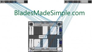 Method 1: connect a pair of 10Gb Ethernet Pass-Thru modules into the blade chassis, add a CNA on each blade server, then connect the pass thru modules to a top of rack convergence switch from Brocade or Cisco. This method is the least expensive method, however since Pass-Thru modules are being used, a connection is required on the TOR convergence switch for every blade server being connected. This would mean a 14 blade infrastructure would eat up 14 ports on the convergence switch, potentially leaving the switch with very few available ports.
Method #2: connect a pair of IBM Cisco Nexus 4001i switches, add a CNA on each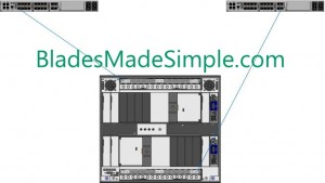 server then connect the Nexus 4001i to a Cisco Nexus 5000 top of rack switch. This method enables you to use as few as 1 uplink connection from the blade chassis to the Nexus 5000 top of rack switch, however it is more costly and you have to invest into another Cisco switch.
The New Approach
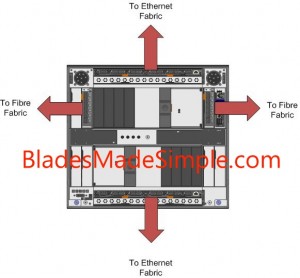 A few weeks ago, IBM announced the “Qlogic Virtual Fabric Extension Module” – a device that fits into the IBM BladeCenter H and takes the the Fibre traffic from the CNA on a blade server and sends it to the Fibre fabric. This is HUGE! While having a top of rack convergence switch is helpful, you can now remove the need to have a top of rack switch because the I/O traffic is being split out into it’s respective fabrics at the BladeCenter H.
What’s Needed
I’ll make it simple – here’s a list of components that are needed to make this method work:
- 2 x BNT Virtual Fabric 10 Gb Switch Module – part # 46C7191
- 2 x QLogic Virtual Fabric Extension Module – part # 46M6172
- a Qlogic 2-port 10 Gb Converged Network Adapter per blade server – part # 42C1830
- a IBM 8 Gb SFP+ SW Optical Transceiver for each uplink needed to your fibre fabric – part # 44X1964 (note – the QLogic Virtual Fabric Extension Module doesn’t come with any, so you’ll need the same quantity for each module.)
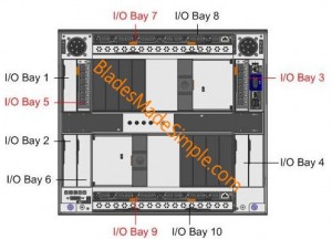
The CNA cards connect to the BNT Virtual Fabric 10 Gb Switch Module in Bays 7 and 9. These switch modules have an internal connector to the QLogic Virtual Fabric Extension Module, located in Bays 3 and 5. The I/O traffic moves from the CNA cards to the BNT switch, which separates the Ethernet traffic and sends it out to the Ethernet fabric while the Fibre traffic routes internally to the QLogic Virtual Fabric Extension Modules. From the Extension Modules, the traffic flows into the Fibre Fabric.
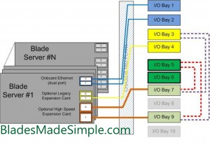 It’s important to understand the switches, and how they are connected, too, as this is a new approach for IBM. Previously the Bridge Bays (I/O Bays 5 and 6) really haven’t been used and IBM has never allowed for a card in the CFF-h slot to connect to the switch bay in I/O Bay 3.
There are a few other designs that are acceptable that will still give you the split fabric out of the chassis, however they were not “redundant” so I did not think they were relevant. If you want to read the full IBM Redbook on this offering, head over to IBM’s site.
A few things to note with the maximum redundancy design I mentioned above:
1) the CIOv slots on the HS22 and HS22v can not be used. This is because I/O bay 3 is being used for the Extension Module and since the CIOv slot is hard wired to I/O bay 3 and 4, that will just cause problems – so don’t do it.
2) The BladeCenter E chassis is not supported for this configuration. It doesn’t have any “high speed bays” and quite frankly wasn’t designed to handle high I/O throughput like the BladeCenter H.
3) Only the parts listed above are supported. Don’t try and slip in a Cisco Fibre Switch Module or use the Emulex Virtual Adapter on the blade server – it won’t work. This is a QLogic design and they don’t want anyone else’s toys in their backyard.
That’s it. Let me know what you think by leaving a comment below. Thanks for stopping by!